On our company's Christmas celebration (December 2013) all employees got a small present: A Raspberry Pi. This was the initial event for me to investigate what (internet of) things can be done driven by this tiny computer.

This blog is to document my findings and to share what others shared with me.

Mittwoch, 29. Januar 2014

Run Raspberry Pi by battery

In my last post we discussed what things have to be considered on running the Raspberry Pi and the motors by battery. I decided to use a 12V battery. Due to the facts that the Raspberry Pi needs a 5V power source and the battery's voltage will vary according to its state of charging we need something to get along to these problems: A step-down constant voltage module. There are two types of step-down modules: Linear regulators and voltage converters.

Linear regulators are used to step-down voltage only for a small amount because it is done by transforming the difference of voltage into heat. This is not very efficient but can be done if there is enough electric current available (for example if your circuit uses a power supply unit instead of a battery). In fact our Raspberry Pi uses a linear regulator to step-down 5V to 3.3V. I found several blogs showing that this regulator can be removed to run the Raspberry Pi at 3.3V because 5V is only needed for USB and the 5V-supply of the connector-unit (doing so breaks your warranty!). Gpio-pins for example also run at 3.3V. But I won't modify my Raspberry Pi since I will also need 5V for other purposes.

Voltage converters work similar to PWM-signals: The source current is switched on and off at a very high frequency to get an average voltage as output. But this frequency would be transported by the current to components running at the output voltage (for example ICs) and disturb their functionality. So the output has to be flattened. This is done by adding inductors and capacitors. This method is very efficient especially if the voltage has to be stepped down extensively. The only limitation is that the difference between the input and the output voltage has to be at least 1.5V to get this mechanism to work.

As I want to preserve as much energy from the battery as possible and the difference between the battery's voltage (12V) and the circuit's voltage (5V) is more than 1.5V I decided to use a voltage regulator. Now to get a constant voltage even if the input varies you need an IC which will handle this properly. I have chosen the LM 2576 T-5.0 (see
http://www.reichelt.at/ICs-LM-2000-LM-25576/LM-2576-T5-0/3//index.html?ACTION=3&GROUPID=5466&ARTICLE=10425&SHOW=1&START=0&OFFSET=500&) which is able to handle currencies up to 3A. Usually the Raspberry Pi needs up to 700mA on average and the circuits needed to control the mowing robot won't need more then 300mA so I also could use the LM 2575 T5.0 which is limited to 1A. But I read that the Raspberry Pi might produce peeks up to 2A so I think using the 2576-IC is the conservative result.

The 2576-IC's data sheet (see http://www.reichelt.at/index.html?&ACTION=7&LA=3&OPEN=0&INDEX=0&FILENAME=A200%252FLM2576T5%252C0%2523NSC.pdf) shows how to build the electronic circuit which is pretty simple:
As suggested in the data sheet a second input capacitor at 100nF (ceramic capacitor - not shown in the circuit above) and a second inductor-capacitor-pair (output ripple filter) should give a good power supply for the Raspberry Pi:

With this post done I shared all information I figured out until now. In the next weeks I will build and test all the circuits shown in my last posts (including this post). I will update each post by appending results, photos and conclusions of applying this knowledge in practice or add separate posts if necessary. So stay tuned…

UPDATE:
I built the circuit. Here I measure the input-voltage (11.27V) provided by a wall-cube-regulator (should be 12V but this is a good test as batteries also supply different voltages depending on their state of charging):
And of course the result (including descriptions of the elements on the breadboard):

Samstag, 25. Januar 2014

Control motors - Part 4: H-Bridge

As I mentioned in my last post I have to wait for the delivery of the parts I ordered. In the meantime I will continue blogging. So what we've got until now is: We have chosen a proper type of motor, we have discovered how to control the speed of the motors and we figured out how this can be done by Raspberry Pi's gpio-pins. If we want to plug these things together we have to buy a test-motor to be sure that everything works as expected.

One of the characteristic features of a motor is the voltage needed to run in full speed. But unfortunately most motors have different voltage values as Raspberry Pis 5V output. Additionally the 5V port gives insufficient power to run one motor let alone two of them (see http://elinux.org/RPi_Low-level_peripherals). So it seems that we need different power sources for the Raspberry Pi and the motors. This would allow us to choose the motor (nearly) independently to the current the Raspberry Pi needs to run. There is one thing to be considered if doing so: the motors voltage value should not be too close to 5V.

Finally the mowing robot's power source will be a battery. For the sake of simplification I decided to connect the motors to the accumulator directly. The controlling Raspberry Pi has to be connected to a battery, too. However, accus usually have voltages of multiples of 1.2V. So you will get 4.8V with using four cells or 6V with using five cells. But the range of voltage for Raspberry Pi's power supply is between 4.75 and 5.25V. Additionally fully charged batteries have more voltage than nearly discharged ones.
So we need a step-down constant voltage module if the batteries voltage is higher than 5V or a step-up if it is lower. Those modules work best if there is enough scope between the source voltage and the destination voltage (I read it has to be at least 1.5V).

So as I have to use a battery different to 5V (at least 6.5V) I can connect the constant voltage module to the motors' accu, too. The only condition is that the nearly discharged accus voltage is at least at 6.5V. I have chosen 12V. The main reason for this is that the motors I want to use (http://m.conrad.at/ce/de/product/233132/) are only available at 6V or 12V and 6V is too less.
I also want to mention that it would be possible to use 8.4V accus and two step-down converters: one for the Raspberry Pi's 5V and one for the two motors. In this situation I could also use the 6V motors. But I read that motors of higher voltages need less electrical current because the electrical resistance is lower as higher the voltage is (this is also the reason for using high voltages in high-tension lines).
Another challenge is to enable the motor to run in both directions (forward and backward). This can be done by exchanging plus and minus. But if the robot has to go backward we cannot unplug the motor and plug it in the other way again. This has to be done by an electronic circuit. Additionally the circuit has to manage the connection of Raspberry Pi's 5V and the motors 12V. Both features are covered by an h-bridge (see http://en.m.wikipedia.org/wiki/H_bridge).

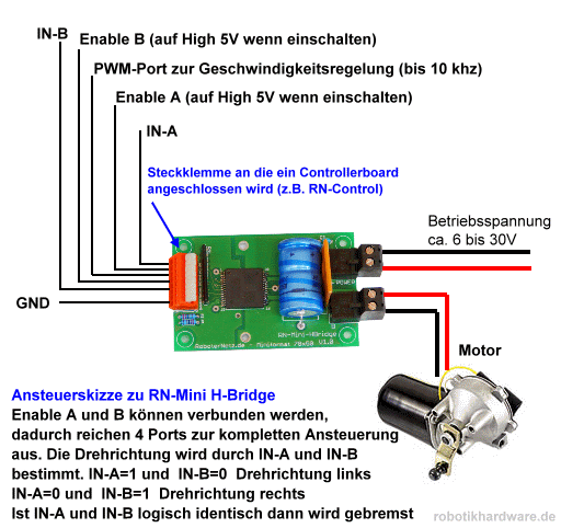
If you do some research you will find out that there are many other things which has to be considered in conjunction with h-bridges: Motors produce inductive currents on stopping which have to be discharged, the PWM-signal has to be applied to the motors power supply, not running at full speed will produce heat which has to be dissipated and also monitored. There are many things which can go wrong so I decided to look for an IC which is able to handle all these things for me. What I found is this http://www.shop.robotikhardware.de/shop/catalog/product_info.php?products_id=89 (I'm sorry this site is written in German). Only a few parts have to be assembled and once done the motor can be controlled by four pins at 5V-level:
  • IN A at high and IN B at low: The motor goes forward
  • IN A at low and IN B at high: The motor goes backward
  • IN A and IN B at high or low: The motor breaks if rotating
  • PWM: Input-pin for the PWM-signal
  • GND: The 5V-level ground
...and four pins at 12V-level:
  • POWER and POWER-GND: The place where the battery has to be connected.
  • MOTOR and MOTOR-GND: The place where the motor has to be connected.
Pretty easy, isn't it?


Once I have received the parts (including the IC used as the h-bridge) I will do the assembling and report about it in an upcoming post.

Donnerstag, 23. Januar 2014

Control motors - Part 3: Digital PWM

During the last days I did some research because I'm about to order several parts needed for upcoming posts. But now this is done and I'm ready to share further findings.

After exploring PWM-signals I thought about how to control pulse width by using Raspberry Pis gpio-pins. At the very first moment it seemed easy: Take four pins and set any binary value controlled by software (0-15 means 6.66% for each step which is sufficient for my needs). A circuit will manage the current flow through resistors which values match the binary bit each gpio-pin represents. But studying the PWM-circuit shown in my previous post discloses that electric current has to flow in both directions through my resistors and using the potentiometer the value of the resistor on the way back is complementary to the value of the one the way there. This is what builds the typical PWM-signal. Building a circuit based on gpio-input behaving in this way seems to be pretty complicated. There has to be a better way to do this.
After a little bit of searching the web I found this page: http://www.spaennare.se/pwmdig.html#chap6. The guy who shared this information (his name is Stefan) is pretty smart and found an indeed elegant way to solve this problem:
The cycle of a PWM-signal can be divided into units which number is defined by the resolution at which we want to control the output current. I my case this is 15 because I want to use four gpio-pins (2^4=16 stages and 15 units between them). Stefan has chosen 100 stages so his circuit is a little bit more complicated as mine will be (but more precise). Each unit can now be at current (called high) or off current (called low). So for example if we want 13.33% output we have to keep the first two units of one PWM-cycle at high and the remaining 13 units at low.
So how could Stefan achieve this pattern? He COUNTED from zero to 100 and COMPARED each value to the requested (and inverted) level of current. If the second value is greater then it is high otherwise low. And this is periodically repeated. If the counter reaches 100 it starts at 0 again. COUNTING is done by the IC 4510 and COMPARISON by the IC 4585. The output of IC 4585 is exactly the PWM-pattern we need.
But his approach has three downsides which I want to get rid of:
First disadvantage is that he uses decimal units (100) which is not a numeric system supported by computers well. Computers use binary numbers because they only know high and low (a bit). You can use 7 bits to represent numbers up to 127 or 6 bit for numbers up to 63. 7 bits wastes some space and 6 bits is to small. So using any potential of two for the number of steps will fit better to Raspberry Pis gpio-pins. So I will use the IC 4029 which is a binary counter instead of the IC 4510 which is a decimal counter.
The second downside is that his circuit needs an inverted input-signal for working properly. Inverting the signal is not hard to do (Stefan gives an example circuit) especially if it is provided by a computer: simply invert the number by software before setting the gpio-pins. But inverting is not necessary as you will see.
The third downside is that Stefan uses 100 stages from 0% (motor does not rotate) to 99% (motor rotates at almost maximum of speed). This missing step to get 100% of speed is not a problem at all. But if you use 4 bits (as I do) every missing step is 6.25% and a maximum speed of 93.75% is a problem!
So what have I done:
In my descriptions above I said that each step is 6.66%. This is because I use 16 stages which represent values from 0% to 100%. Common binary counters (as IC 4029) use four bits and allow cascading for counting bigger numbers than 15 (they start at 0). As we use four gpio-pins we do not need to cascade (as Stefan needed to count up to 100) what simplifies the circuit.
Next is that I do not invert the input signal. So I also have to choose another output pin (in fact two of them: = and >) of the IC 4585 to get a proper PWM-signal.
The last action is to preset the counter at 1. This reduces to number of units by 1 but raises the output of the input-signal "1111" to 100%.
So at the moment I'm waiting for receiving the parts I ordered (including ICs 4029 and 4585). As soon as they arrive I will test my theory and update this post by appending the circuit and pictures. So stay tuned!

UPDATE: I added another post ("Control motors - Part 3: Digital PWM - Part 2") to comment what happened during building the circuit.

Freitag, 17. Januar 2014

Control motors - Part 2: PWM

"Control motors - Part 1" showed that there are less downsides on step motors than on gear-backed motors. Nevertheless to move a mowing robot of a weight of about 10kg (sometimes uphill) we need a force of about 2-4 Nm per wheel (having a diameter of 12 cm). Only gear-backed step motors can put about this level of force and those are rare and expensive. If you put gears between a wheel and a motor the motor has to rotate at the rate of the gears faster to achieve the same rotating speed of the wheel. A step motor needs 200 impulses to turn its axis around. So using a gear-backed stepper with a gear-ratio of 1:50 results in doing 26315 steps per second to gain a speed of 1 meter per second. As I found in the web it seems that stepper motors are limited to 2000 sometimes 3000 steps per second. Even if there is a stepper out there which is twice as fast it would be 4-5 times to slow. Another fact is that step motors have less torque the faster they turn. So I think this is it: I need to use ordinary gear-backed motors.

So the first challenge at using non-step-motors (ordinary dc-motors) is to control their speed. If you look at the specification of a dc-motor you will find the voltage they need to run. This value is valid for the full speed. If you want half of the speed you have to halve the voltage you putting on. But how can we achieve this by using Raspberry Pi's gpio-pins? As I said in my preceding post we have to use PWM (pulse width modulation). But what is PWM and how does it work?

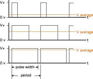
PWM means switching an electric current on and off very fast. Depending on the frequency of this switching the average voltage changes. This is very useful for digital controllers (as our Raspberry Pi is) which only know 0 and 1 (current off or on).
But PWM is a special way of switching current on and off: Within a period of a choosen frequency electric current is switched on and off proportionately. I found this image at http://www.societyofrobots.com which shows how it works very well:

These three examples use all the same frequency but different pulse width (electric current is switched on) and they produce different values of average voltage.

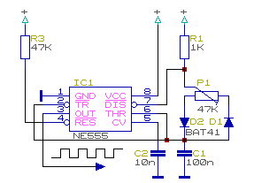
For my first actual project I decided to build PWM as a curcuit. In the electronic tutorials I looked at the NE555 IC was used to produce timed signals. I bought the parts for exercising those tutorials, so let's ask the world for instructions. I googled and found http://www.domnick-elektronik.de/elek555.htm (written in german) showing this tiny curcuit:

I built this curcuit on my breadboard and put a LED and a proper resistor on OUT (pin 3 of NE555). Guess what: The LED dimed by turning the potentiometer. For educational reasons I replaced C1 by 10μF and voilà: The LED blinks in the way of the PWM signal.

UPDATE:
Here is a video showing the result:

Donnerstag, 16. Januar 2014

Control motors - Part 1: What type of motor to use

The first thing I want to do is to control a motor. For a mowing robot we need several motors: Those which drive the wheels and the one which drives the cutting-rotor.
Maybe this is the right moment to think about steering: As other robots do, I want to use three wheels. Two wheels at the back which drive the robot and cannot turn. One wheel at the front which is not driven but can be turned around at random. Here is an image: http://www.ratgeberzentrale.de/uploads/tx_news/15260_23529_Bild3.jpg. It does not show the configuration of the mowing robot I have in my mind but it does shows how the three-wheels-concept is meant.
In this configuration steering to the left is done by braking the left wheel or accelerating the right wheel. Steering to the right vica versa. An advantage of this technique is the ability to turn around nearly in place. A disadvantage is the need to control two motors precisely which means to use more gpio-pins than if we would drive our robot like a common car (I will explain the reason for this in an upcoming post).
So how is a motor controlled by an electronic circuit?
One possibility is to use a stepper-motor. These motors allow to turn a predefined step (for example 1.8°) forward or backwards. Repeatingly doing steps results in a continuous rotation. Speed is controlled by the interval of those steps.
The advantages of those motors are that they are easy to control and the force needed to do a step (even if you are driving uphill) is regulated by them self. Another feature is that they are able to hold their position even if a force tries to change the position. A downside of this is that they consume energy even if they are not rotating. Another disadvantage is that step motors are not built to rotate fast. They are made to move sheets of paper in printers forward and backward or support balanced robots for example. So it might be that this kind of motor is not suitable for our application.
The second possibility is to use back-geared motors. They are quite simple: put voltage on it and the axis starts to rotate. This kind of motor is not able to rotate slowly so the gear slows it down and brings additional power due to its gear ratio. This sounds pretty good but there are downsides!
The first one is the way to control the speed of rotation. This is done by reducing the voltage. If you have a regulator this is done easily but how can this be achieved by Raspberry Pis gpio-pins? The solution for this is PWM (pulse width modulation). This technique is supported by Raspberry Pi nativly but only for one device not two (motors). So we have to build PWM on top on usual gpio-pins. The second downside is that driving uphill would slow down the speed  of the motor and voltage has to be increased to compensate the reduction of speed. To do so it is necessary to measure the current speed - also not so easy.
As you can see the decision is not easy to come.

How Raspberry Pi can control things

Our Raspberry Pi supports several ways of interacting with other systems. As we have to develop electronic circuits to interact with the environment we have to use the gpio connector (see image at http://learn.adafruit.com/adafruits-raspberry-pi-lesson-4-gpio-setup/overview). Gpio means "general purpose input output". This is the easiest way to control other circuits (output) or to get feedback from them (input) into the software running on the Raspberry Pi.
What is easy to me? Easy means that output-pins of the connector can be switched on or off by software commands. Current flows or not, there is nothing in between. In the same way input pins can only measure whether current is off or on. This is quite useful when we develop circuits because we can easily simulate active and inactive pins by using a micro-switch. Pushing the switch lets the current flow and releasing it stops the flow. So we are able to build and test circuits without them being really connected to the Raspberry Pi. Connecting the Pi and replacing our manual control by proper software can be done later.
But what about values between on and off - for example the speed of a motor we want to control or the distance to a barrier we want to measure? Those values have to be translated by using more than one pin. This technique is called analog-digital-converting. If we want to control 4 levels of speed (of a motor) we have to use two pins: 0% (00), 33.3% (01), 66.6% (10), 100% (11). If this is not as accurate as needed we can add another pin: 0% (000), 14.3% (001), 28.6% (010), 43% (011), 57.3% (100), 71.6% (101), 86%, 100% (111). As you can see this procedure needs a lot of pins and the number of available pins is limited. So we have to see whether we need a work around or not (for example a port expander).

Mittwoch, 15. Januar 2014

The goal

In the past I always needed a reason for doing something. Also in this case. So what useful thing can be created using a tiny computer? Nothing, if it doesn't interact with its environment. Interaction by reading or writing information to other computers is well known so another challenge is needed: Internet of things.

As I understand it "Internet of things" is every device or gadget driven by internet technologies. In the huge number of possibilities I picked something I could use well: A mowing robot. Related to the Raspberry Pi this will conduct me to a lot of challenges like electronics in general, controlling motors to move the robot, sensing the robots environment, building a battery-backed system and finally writing the software needed to steer through the garden safely.

Maybe this goal is to high to reach, but it will be a lot of fun trying. So let me see, what can be achieved...