On our company's Christmas celebration (December 2013) all employees got a small present: A Raspberry Pi. This was the initial event for me to investigate what (internet of) things can be done driven by this tiny computer.

This blog is to document my findings and to share what others shared with me.

Freitag, 25. August 2017

sauna temperature measure device

Two years ago I built a sauna. Since our house has no basement the sauna is not within the house. It is in a detached house:


Especially in winter we don't want to waste to much energy and use the sauna as soon as the temperature is OK. So in the last two years we needed to guess after which period it is OK or go outside to check the temperature.

Now I installed an ESP8266 module to measure the temperature so I can check from inside the main building.

This is quite simple and takes just a few steps:
  1. Buy a DS18B20 temperature sensor
  2. Buy a nodemcu ESP8266 module
  3. Connect them as shown
  4. Install the software (see GitHub)
  5. Install the device in your sauna
 That's it 😊

How to connect the sensor
The sensor placed in the sauna
The ESP8266 module in the sauna
The result

Samstag, 19. August 2017

Irrigation management

We built our house only a couple of years ago. This year we wanted to build a terrace in order to get more out of our garden. Caused by the position of our well which we use for irrigation and the size of the new terrace, the well would be entirely hidden by the new terrace. It became necessary to install an irrigation system because once the terrace will be finished I won't be able to bring tubes into the well. Unfortunately irrigation systems are expensive so I decided to build it on my own.

Most of the irrigation systems on the market use solenoid valves at 12V or 24V. Some of them use rotating valves. Both is necessary because they need to be able to switch tubes of big diameters (e.g. PE pipes with 3/4" or 1" inner diameter or even more) and thus need power. In a normal sized garden (mine is about 800m² of lawn area needing to be watered) the region watered by each irrigator is not that big. A smaller tube diameter of 1/2" should be sufficient. If your pump provides a lot of water you can even choose to turn on two or three sprinkler at the same time, each connected by a 1/2" tube. You just have to use a bigger diameter for the tubes connecting the pump and the solenoid valves so each line is supported by enough water.

Nevertheless I want to run my irrigation sytem on top of the RaspberryPi which is powered by a 5V USB supply. There are no valves using 5V, but there are valves using 230V AC. Of course there is 230V AC available: the same plug socket which my RaspberryPi is connected to. But be aware: 230V AC is powerful but also dangerous and using it requires a lot of responsibility and carefulness - do not forget to unplug the 230V line after each test! Lucky for me the friendly chinese store got some cheap solenoid valves using 230V.

solenoid valves connected to the main water support line
(ignore the metal stripes on the wall - they are not part of the irrgation system)

So what's next? I used a relay panel to switch the 230V lines for the solenoid valves. I connected it to a level converter because the panel needs 5V inputs but the RaspberryPi only got 3.3V. It turned out that a converter is not necessary because the relay opens the N/C (normally closed) circuit once the input pin is pulled to GND. So the relay panel can be connected to the RaspberryPi directly. The photo shows the part connected including the level converter.
the RaspberryPi connected to the relay panel which is connected to the solenoid valves

The box is only for development. It is necessary to use a plastic box locked by screws to be sure the 230V lines are entirely hidden and children won't reach them! They are a danger to life!

At last a software is required to control the valves/relays. For a first draft I wrote a simple Java program which uses a property file to read the configuration from (see GitHub: https://github.com/RasPelikan/IrrigationManagement). It has a web UI for basic interaction like stopping/starting a certain sprinkler, pause an active irrigation cycle or shutting down the RaspberryPi. The software is started at boot time using the cron daemon.

So that's it. See it in action:
switching two sprinklers using the web UI

Right now the software supports GPIO based irrigators (switched by relays as mentioned above) and URL based irrigators. I bought some ESP8266 modules at the friendly chinese store mentioned before and wrote a simple Lua script (is part of the GitHub repository) which switches relays on calling an URL. I will use them to extend my irrigation system into the peripheral regions of my garden. This works at the bench and I will do another blog post once I can show it in action.

PS:
I also found a "ready to use" open source software on GitHub called sprinklers_pi. It seems to be nice and it should work straight forward using my relay switched valves. So I will give it a try. There ist also an open issue for ESP8266 based irrigators, but it does not work yet.

Mittwoch, 19. April 2017

ATX power supply

I began to think about the things necessary to build a table tennis robot. Next to the construction itself a lot of motors are needed!
I found a motor including a mounted wheel for accelerating the ball - it consumes 500mA at 3V. A second motor is needed for applying the spin. I need a lot of servos for different tasks, some are weak (consuming 150mA at 5V) others strong (consuming 1A at 5V). The RaspberryPi itself will need approximately 1A at 5V. The last part is a stepper which will drive the push mechanism to move the balls to the accelerating wheel.  That stepper will consume about 1A at 12V. So I will need a lot of current at 3V (1A), at 5V (~5A) and at 12V (1A).
But wait a minute: aren't those voltages provided by a regular ATX power supply? Yes they are. Except 3V but 3.3V will work as well.

There are some projects out there providing an ATX power supply for driving a RaspberryPi. But wouldn't it be boring simply ordering another part? It is much more interesting to build a circuit on my own. And this is what I did:


On GitHub you can find all information how to build it on your own:
https://github.com/RasPelikan/raspberrypi-atx

Sonntag, 26. Februar 2017

Table tennis robot

Unfortunately it is a long time ago that I wrote a blog post. I was on the way to build a mowing robot.

On the way I had to invent a lot of things. Some of them are:

  • For Pi4J:
    • Pull request - Added MCP44xx, MCP45xx and MCP46xx families to pi4j-i2c-devices
    • Pull request - New Concurrency in I2CDeviceImpl and I2CBusImpl
  • AVR-projects:
    • Eclipse-Plugin - Use usbasp programmer to show up UART in Eclipse
    • Gadget - A silver screen remote controller
But since I could not tell my wife when the mowing robot will mow the gras in our garden, she did not want to wait any more and I had to buy a ready-to-use product. And yes, it mows the garden.

So what now?

In the last fall my sun started playing table tennis. Due the fact that this is some sort of "farther and son"-thing I also learn table tennis. And after the first lessons I recognized that it would be fantastic the use a table tennis robot for the training. A robot would be able to place every ball to the same spot, with the same speed and the same spin. So you can focus on refining your technique. As always you can buy a cheap model which won't make you happy on the long run or you take a lot of money and buy a good model. Or, you DIY :-) ... which not necessarily means that you will be happy on the long run :-)=)

In the very beginning a saw a lot of Youtube videos showing DIY table tennis robots. But I also looked videos of professional robots to get inspired. And after a couple of days I knew that I want to build a robot which one day might be better than professionals. But step by step: 
  1. The first "version" should be similar to those cheap models: They sit in the middle of the table and shoot the balls to the left, to the middle or to the right. The cheap robots only know top-spin oder under-spin. My robot should be able to create every spin (top, under, left, right, combinations). Additionally it should also be able to shoot faster or slower in combination with up- and down-directions. And, of course, a ball recycler: A net which collects all the balls I return during practicing and brings them back to the robot to shoot them again.
  2. Once this works I want to build a rail on which the robots moves. This should enable an advanced training mode and generates shoots like a human player would do. Additionally the ball-cannon should be able to move up and down. Especially for this version I can reuse a lot of things I already bought for building the mowing robot.
  3. And in the end I want to add a RaspberryPi camera module to track the ball and move the robot not only in predefined ways. It should move along the returning ball to shoot the next ball from the place the returned ball hits the collector net. This should give a feeling as playing with a person.
In the last three months I tried some of this features to see whether I could make it. And yes, it seems to be makable. So I will report about the progress, the problems and the solutions in the upcoming posts.

Samstag, 10. Januar 2015

LPS - Sending radio signals

A lot of things have to be considered if you want to send and receive a signal. I want to list those and my conclusion about them.

1. Radio-traffic

I intend to send a signal to a reference-location and the reference-location should return the signal. Doing so brings up two problems:
  1. The frequencies which can be used for general-purpose transmissions are limited. For example within the EU 433Mhz or 868Mhz may be used. So every garage-door-opener or weather station uses one of this frequencies which means you will receive a lot of noise made by other people's gadgets.
    To filter signals sent by the mowing robot to a reference-location I have to encode the data in a certain way which can only be decoded by the reference-location. To do so dedicated ICs can be used. I prefer HT12E as encoder and HT12D as decoder. But there are also other products available like PT2272 (Encoder) and PT2262 (Decoder). Those ICs encode a couple of bits into a stream signed by an "address". The decoder-ICs are listening for a certain "address" and spit out the bits set to the encoder once the address matches. In short: You don't have to be concerned about other people's signal-noise by using those ICs.
     
  2. Another issue is about bidirectional communication. Every communicator needs a sending- and a receiving-modul. So if the the mowing robot sends out a the signal its own receiving-modul will pick up the signal, too. In the same way the reference-location's receiving-modul will pick up the response.
    Sending any signals occupies the receiver. This means that the mowing robot cannot receive the response during transmission. At a first look this does not seem to be a problem, but for longer distances the duration of the sending has to be increased to guarantee a successful transmission. In this situation it might be that the success is already there in the very first milliseconds of sending. If the reference-location starts responding immediately the mowing robot's receiver will no see the signal because its own sender is transmitting a signal much stronger.
    This situation can be avoided in two ways: The easier one is to use another frequency for sending the response. Unfortunally I could not find an easy-to-use sending-modul available in both frequencies. So I have to use the second way which is by responding to the robot's signal after a certain amount of time, when the reference-location can be sure that the robot's transmission is complete. The downside of this way is that a lot of time is wasted. At the moment I cannot tell for sure but I guess using two frequencies is about 2-10 times faster. At a distance of 25 meters this means the robot will be able to contact only 3-4 reference-locations instead of 6-8 per second.
2. Sender-/Receiver modules

I was looking for cheap modules and found this:
  • Sender = FS1000A
  • Receiver = XY-MK-5V
They are pretty cheap and use very little current in standby mode (available at DX or Semaf). The amount of energy needed to run a reference-location is a critical issue. I will write about this later. For the moment: less is better.
Above, I mentioned that I could not find those modules at 868Mhz. There were other modules which do 868Mhz but they has to be connected by I2C or SPI. A pair of the modules introduced here can conceptionally be used in the same way as a cable. This is pretty easy and can be used in any electronic circuit without the need for a microcontroller.

The most websites reporting about the FS1000A-module tell that the range of transmission is from 2 to 200m. The actual value depends on several attributes:
  1. The module can be run at different voltages (3V to 12V). A higher voltage means bigger range.
  2. For the receiver-module a 5V supply is required so it would be easiest to apply 5V to the sender-module, too. Due to the noise at the frequency of 433Mhz I cannot tell how far the signal reaches, but something above 50m.
  3. The modules itself may send only a couple of centimeters. They have to be extended by antennas (both sender and receiver) to gain more than 1m. I soldered a 1/4-antenna (simple cable in a 17.3cm length) at the proper pins.
  4. At the outer ranges the signal is weak. So even if the range is 100m I won't be able to read any data or identify those data as mine at 100m.
  5. I was able to build a stable communication at a distance of 30m using a 5V-supply. For that I have chosen to stretch the signal as much as possible (lowest oscillation frequency - see datasheet of HT12E and HT12D). Additionally I set the enabled-pin of HT12E to active for 90ms. In this time the stream generated is repeated again and again. Usually one or two of those sequences could be read by the receiver at a distance of 30m. If the noise was low it worked up to 50m.
  6. Noise: I've mentioned it already above. The noise influences the quality of transmission and therefore the distance of possible communication. This has to be kept in mind for processing the ranges for position triangulation: The circuit will measure different values for the same distance in dependence to the current environment conditions.
3. Transmission attributes

I already mentioned that it is necessary to increase the time of sending for longer distances. The greater the distance between receiver and sender the more other radio-traffic of the same signal strength (of other people's gadgets) will disturb the transmission.

In addition to this effect the speed of transmitting has to be reduced for longer distances. This does not mean to modify the frequency. The HT12E-IC encodes the information I want to transmit into a stream of 0 and 1 digits. If I have longer distances the whole transmission has to be stretched not repeated more often. So for short distances a 1-digit might be successfully read if it is 0.1ms but for longer distances the noise scrambles the 1-digit so it has to be 1ms to be detected as a 1.

In the first try I will use constant duration and constant speed of transmission. Each value is selected so that it works at the longest distance I want to reach. To optimize the number of reference-stations to track per second I will try to decrease the duration and increase the speed of transmission in dependence of the distance. I intend to do this by transmitting the distance to the reference-station because the strategy I want to use for measuring the distance does not require transmitting a specific value - it only requires transmitting anything. So why not sending a value which can be used for optimization?

What's next? Let's take a breadboard and build a reference-location. Oh, wait. All my breadboards are in use. It seems I have to get them free. Stay tuned to what this means ;-)

Montag, 5. Januar 2015

LPS - The idea

For the mowing robot it is vital to know at every point in time at which location within a certain area (the garden) it is. Most robots that are available in the stores need cables put into the ground to define this area. Thoses cables are detected by the robot so that it knows when it reaches the border and has to turn around. The robot never knows its exact location and drives around at random. To find the base-station a special tracking-cable has to be placed which is passed by the robot from time to time. My garden is pretty big and it would be difficult (but not impossible) to place those cables. Additionally robots waste a lot of time and energy driving at random since they pass a lot of locations several times.

I want my robot to drive a certain path so that it passes every specific location only one time. For that reason I need some sort of ranging. The borders of the area should be known by the robot. If there is some sort of ranging the borders can be honored by it. How does the robot know about the borders? There will be a special administration-mode in which I will steer the robot by remote-control along the borders and it will record those positions.

So the requirements for location-tracking/ranging are:
  1. The resolution has to be close to 10cm.
  2.  Power consumption has to be low.
  3. Most of measuring-work should be done by a circuit to relieve Rasperry Pi's CPU.
The first idea I had is to use GPS. But GPS does not meet my requirements well:
  1. Standalone-GPS resolution yields about 2.5-1m (depending on the number and kind of satelite-signals receiving). I was wondering about this since geometers use GPS to place landmarks up to a resolution of 1cm. Searching the web gave me the answer: They use differential GPS. D-GPS uses a second GPS-receiver at a reference-location. The raw-signals of both locations can be used to get more precision relative to each other. Geometers use public reference-stations which provide their raw-signal through a special internet-protocol. But those services are not free and building my own reference station is too complicated.
  2. GPS-receivers consume a lot of energy (at least 100mA at 3.3V - this is not very much, but less would be nice).
So if global positioning is not suitable maybe some kind of local positioning will be? Local positioning works by triangulating distances to at least three reference-locations. But how to get those distances and what kind of reference-locations?

One possiblity is to use sonic. An example for a ready-to-use module is HC-SR04. But there are limits prohibiting sonic for local positioning:
  • The signal has to be directional, but usually the direction of those reference-locations are unknown.
  • The maximum range is 3m - the distances in my garden is bigger than 3m ;-)
  • Objects between the reference-locations (f.e. children's toys) disturb the signal.
So I will use HC-SR04 for collision prevention but not for local positioning.

So what's left? Radio! But radio-signal cannot be used in the same way as sonic is used to measure distances. HC-SR04 is measuring the time-gap between sending and receiving the signal. This works because sonic is a slow signal. Radio works at the speed of light so a distance of 10cm is passed in the time of the 2,997,924,580th part of a second. This is too short to be measured.

So this is the idea:

I build reference-locations which receive radio signals sent by the mowing robot and return those signals immediatally. The robot will listen for the response. The mowing robot's signal can only be returned, if it is strong enough to reach the reference-location. So I increase the signal strength in a loop by a very small amount starting at zero. Once I get an answer I know the signal strength which is in any correlation to the real distance. If I do this for at least three reference-locations and I know about the correlation between the signal strength and the distance I am able to calculate the local position. So far so good.

To proof this, three things have to be done:
  1. Build the robot's sending-unit and a reference-location-unit.
  2. Test whether increasing signal-strength for measuring the distance is reliable/reproduceable.
  3. Learn about the correlation between signal-strength and distance.
The next post will report about the steps I take to get this proof of concept.

Dienstag, 13. Mai 2014

Building PCBs - Part 2: Two sided PCBs

In my last post I used the toner transfer method to build a PCB. Sometimes the arrangement of nets of a layout get pretty complicated or impossible to figure out. Even auto-routing fails or results in arrangements hard to work with.
In this case it might be better to use a two sided layout: Whenever a net cannot reach its target you can use vias to switch to the other side and go on easily. For the H-bridge IC I use to run motors (see Control motors - Part 4: H-Bridge) I need a two sided PCB so let's see how this can be done using the toner transfer method.

Two sided PCB
First of all you need PDF-files of the mirrored layout of the top and bottom layer. They have to be printed to toner transfer paper. Afterwards I punched the 3mm holes at the edges of the layout which are needed to screw the board into a box. Now I put one layout on the copper and used a permanent marker to amplify the holes made before. After this you can remove the layout and you will see the positions for drilling those holes. The next step is to drill the holes.

Now you have two layouts printed to toner transfer paper and the board - all parts with holes at the same position. After cleaning the board the next step is to iron the layouts onto the board. Now I arrange the first paper using the holes: they have to match exactly. Next I put the iron on the stack for some seconds to make the paper stick on the copper. After this the board can be flipped to repeat the procedure for the second side using the remaining print. If both papers stick well you can flip the board several times to ensure each side is ironed as explained in my last post. The rest of the story is the same as for single sided PCBs: Peel off the media, etch the board and remove the residing toner.

The upper side of the board after toner transfer...
...and the lower side.
(the dark areas are minor defects I fixed using permanent marker)
After etching the board you can drill the holes needed for common elements or vias. Do not drill through the board. Sometimes the position of the layout is not as exact as it should be and drilling through could break nets of the second side. I drill from both sides to the middle of the board - similar to  digging a tunnel. If the hole does not match exactly it does not matter. The elements can be soldered even if the hole is displaced a little bit.

After etching and drilling you can see how exact your work was. I'm satisfied :-)
First note: If you prefer transparent film you can orientate the layout as shown in this post: http://www.instructables.com/id/Two-sided-PCB-using-toner-method/.

Second note: You might asked yourself which kind of vias I use. None! I build vias by soldering strand on both sides of the board. Before doing this I put the board on two stencils. This builds a distance which helps to ensure that both sides can be soldered well. After soldering the excrescent strand can be cut off.

Dienstag, 6. Mai 2014

Building PCBs

A lot of things happened since my last post! I got a lot of new modules needed by my mowing robot (RF, distance sensors, 3-axis compass, charging IC, and so on). I have to investigate them before I can use them. This will be very interesting and a lot of fun ;-)
Unfortunately my breadboards are full and I have to bring all the stuff to circuit boards. So the next step is to learn how to produce those boards.

First of all you have to design your board. There is a lot of free software available. I tested Fritzing and Eagle and both do a good job. The disadvantage of Fritzing is it's limited elements-library and the disadvantage of Eagle is it's complexity since this is a professional tool. So I will use Fritzing for simply boards and Eagle for complex ones.
Both programs offer to order boards for professional production. This is pretty expensive although the boards offered by Fritzing and Eagle are low-cost-boards. So what is the solution? DIY!

Usually the nets of circuit boards form by etching copper of non-conducting areas. But how to "tell" where copper has to be removed and where not? Professional boards are created by using light exposition: the copper is hidden by a layer of light sensitive paint, the inverted board will be printed on a transparent film used to expose the board and acid will remove those exposed areas (and the nets resist).
This also can be done at home but at home it is not that easy:
  • The exposition can get blurred due to shadows if the film is not fully plain.
  • You see errors and mistakes not until the board is etched. So erroneous boards only can be trashed.
  • Boards coated with light sensitive paint are much more expensive then boards without that layer.
So DIY guys figured out another way: The toner transfer method. This technique is taken from bringing images to T-shirts or cups. The layout is printed to some sort of media using a laser printer and afterwards pressed under heat onto the target. The toner melts and goes to the target. This works best if the target's surface binds the toner better then the transfer media does. For T-shirts and cups special transfer paper is available.

For copper boards it is a little bit more complicated but not much. Most guys out there use any sort of glossy advertising media. After printing (mirrored) it has to be ironed onto the board. Afterwards it has to be put into water (for about 10 minutes) so the media can be rubbed off. There is no instruction which media works best - it depends on your laser printer. Some media is too thin and will not work. Some media binds the toner too much and paper cannot be removed completely. Additionally you put paper into your printer that isn't meant to be used in a laser printer and may damage the printer.
Instead of advertising paper transparent film for overhead projectors can be used. This works good but not reliable good. So at the end I managed to get this special toner transfer paper (used for cups) which works best for me.
Anyway: you have to find out what works best for you. This may be a little bit frustrating but you can be sure that there is a way for every laser printer.

How it works:

  1. Clean your board

    This is essentially for the binding of the toner. Any bit of dust will lift the paper and the toner won't bind! Any fingerprint brings tiny bits of oil onto the board and the toner won't bind! So clean the board precisely and keep it clean.

    I do a three-step cleaning. First, I use stove cleaner and scrub the copper in small circles. After this the board has to be washed and dried. Second, I use steel wool to polish the copper. Third, I use Acetone to remove any oil. It seems to be essentially to use a clean board otherwise the toner does not bind well.
     
  2. Prepare the transfer media

    I use that special transfer paper. In my case there are four things to take care of:

    First, print the layout mirrored and tell your printer to use as much toner as possible. Second, toner transfer paper is very soft. I can see patterns of the laser printer's transport-wheels on the paper after printing. These patterns decrease the quality of the printed layout in this regions so you should avoid printing in this regions by choosing a proper position. If the layout is too big to avoid this then try to reduce the number of SMD-elements or other small things in this regions. Third, the paper cannot be reused so print the layout as many times as possible on one sheet. Maybe your first try fails and you need another print for the second take. And fourth, avoid touching the transfer media to reduce oil of your fingerprints.
     
  3. Iron the layout onto the board

    Put the transfer media on the board with the layout down to the copper. Put some sort of cloth on it. Preheat your iron. The toner starts to melt at approximately 180°C. This is usually the setting between cotton and linen. Which temperature is properly also depends on the thickness of the transfer media and the cloth. Put your iron onto the stack and wait 5 seconds. Now the layout sticks at the current position and you can start to move around. The bottom of the iron is not hot equally so you also have to turn the iron around. Put some pressure on the stack. How much depends on the thickness of the transfer media and the cloth. Thicker means more pressure. The whole layout should contact the copper equally over the time of ironing. You should stop ironing if all regions of the layout are at 200°C. You might ask when this is achieved and I have no answer for you. You will see whether it was too hot, too long or too much pressure if you remove the transfer media. If so the toner has melt to blobs, especially at bigger areas of toner, and the borders are not clear.

    One trick I use is to vary only one aspect: I always use a timer to count the time of ironing and stop always at the same time. On different tries I only change heat or the pressure. This should help to figure out what your personal best settings are.
     
  4. Remove the transfer media

    Wait for cooling down the board and peel off the transfer media. If your media is transparent film you can use some ice because the toner and the media decreases differently on cooling down rapidly and the toner will lift off from the film almost completely.

    Review your board carefully! Some failures can be corrected by using a permanent marker. Take care that all nets are separated to avoid shortens. If there are nets together (for example near SMD-sockets) you can scrub the toner away by using the spot of a sharp knife.

    If the result isn't satisfying then try again. Remove the toner using Aceton and start at step 1. It is better to repeat the process then trashing a board after etching it. It took me several approaches the get a useful result! So don't be inpatient.
     
  5. Etching the board

    This is quite easy. I use Natrium-Persulfat. It is easy to handle and easy to store. Some acids are gassing so you cannot close the canister completely which means you have to store it outdoor since the gas is poisonous. Natrium-Persulfat can be stored in a bottle made of glass or plastic. But keep it away from children - it is an acid!

    The only disadvantage of Natrium-Persulfat is that it works best at 50°C. So I put the liquid into microwave oven for some seconds and put it on a towel afterwards to keep it warm as long as possible. If it cools down too fast you can but the tank into hot water until temperature is properly again.

    After about 10 minutes the board is ready. Take a closer look a nets which are close to each other to be sure that all copper is gone. I use my cell phone's camera which takes nice pictures much more detailed than I'm able to see without any optical support.
     
  6. Remove the resisting toner

    The last step is quite easy. Use Aceton to remove the toner. And after this the board is ready for further steps (for example drilling the holes).
Here some pictures I've taken:
My first try using a transparent film as transfer media
Another try: You can see light spots where dust was between the transparent film and the copper
Sometimes toner resists on the transparent film.
Special toner transfer media. Click to enlarge to see the patterns of the laser printers transport wheels.
A layout on copper using toner transfer media. Good and reproducible quality.
Etching the board - after 5 minutes.
Etching the board - after 8 minutes. Watch the bubbles!
Etching the board - after 10 minutes. It is nearly done - there is some copper left (click to enlarge).
Waiting for etching the last bits of copper.
The final result after remove the toner - pretty nice!
Another try using toner transfer paper: I wanted to know how good it is using bigger layouts.
The board you see is a breakout-board for TSSOP-14 ICs. I made a couple of them to get some practice in soldering SMD ICs. But this is another story...

Samstag, 8. März 2014

Control motors - Part 3: Digital PWM - Part 2

When I wrote "Control motors - Part 3: Digital PWM" I thought everything would work fine but time told me different (in German we say: theory is gray but practice is colored).

The first thing I built was the clock. To make development easier I used a slow clock and put a LED at the output to visualize the signal:
This was pretty easy.

The next step was to install the counter. One thing I had to change was to count down instead of up because presetting to 1 by using the cascading output did not work: the signal is high from the beginning of 0 until the end of 14, becomes low in the middle of 15 and high again at the end of 15 (which is equal to the beginning of 0). I had to invert the signal since the preset-pin is low in inactive state but this means that the rising from low to high used to preset a value is in the middle of 15 - not at the end! This shortcuts the last unit.
A possible solution could be preseting the value asynchronously (which means to tell the IC within a clock-cycle to use the presetted value at the beginning of the next clock-cycle) but unfortunately the ICs I bought did not support this feature. Another solution is to delay the signal for the half of a clock-cycle by inserting a capacitor. This didn't work either. Additionally this way seems unstable to me. I always prefer to use things in the way they ment and if an IC does not support a feature I have to find another which does.
At the end I had to count from 15 to 0 and preset the value to 15 once 0 (= minimum-pin active) is reached:
The LEDs from right to left: Bit 4, bit 3, bit 2, bit 1 and the clock-signal. The IC counts from 15 to 1 and then starts at 15 again.

In the last step I added the comparator IC. I simulated the input-values (the percent of the PWMs duty-cycle) which will be given by Raspberry Pi's GPIO-pins by using four microswitches - each for one bit. Let me show you the possible input and output-values:
Signal sent by GPIO-pins Condition Output-signal
0-0-0-0 = 0 > or = to counter always 0 (= 0%)
0-0-0-1 = 1 > or = to counter 1 if counter is 1 otherwise 0 (= 6.67%)
....
1-1-1-0 = 14 > or = to counter 1 except counter is 15 (= 93.33%)
1-1-1-1 = 15 > or = to counter always 1 (= 100%)
As you can see this is a clean PWM-signal from 0% to 100%. And here is the video showing the signal:
In the middle of the breadboard is a blue LED showing the PWM-signal. At the beginning there is no light because no microswitches are pressed which means input 0-0-0-0 (= decimal 0 = 0%). Then I pressed the switch for bit 1 which means 0-0-0-1 (= decimal 1 = 6,67%). Next I pressed the switch for bit 2 which means 0-0-1-0 (= decimal 2 = 13,33%). Afterwards I pressed the switch for bit 3 which means 0-1-0-0 (= decimal 4 = 26,67%). And finally I pressed the switch for bit 4 which means 1-0-0-0 (= decimal 8 = 53,33%). To complete the row I pressed all switches additionally which means 1-1-1-1 (= decimal 15 = 100%). In every state the output-LED shows the proper duty-cycle.

At the end I replaced the big capacitor of the clock by a smaller one and the LED switched from blinking in the rhythm of the PWM to lighten more or less brighter - as expected. But suddenly the 0% stage was not "no light" instead it was slightly lightening even hard to see. Where is this current coming from?
This short video shows the breadboard in the dark. The clock-LED turns on and off so fast that it seems to be turned on continuously. The blue-LED which shows the PWM-signal is slightly lightened although the input-signal is 0-0-0-0 (no microswitches pressed).

Before I tell you, I have to admit that I had an error in reasoning: For the motors I want to use I have to apply a 2kHz PWM-signal. So I bought a capacitor for the clock-IC (NE555) to produce this frequency. But in fact if the desired PWM-frequency is 2kHz and we divide each cycle into 16 steps the clock for driving the counter-IC has to run at 2*16 = 32kHz.
Finally I could figure out that what I saw was the result of something called glitch. It occurs if the rising from low to high is to slow and the IC is to slow or clock signals delay due to long distances. So rising from 2kHz to 32kHz made glitches visible. As suggested by Stefan (see "Control motors - Part 3: Digital PWM") I replaced all ICs by pendants of the 74LS series. This didn't solve but cleared out the problem as these ICs switch faster:
Every time a cycle completed (counter has reached 0 and will be presetted to 15) the glitch is visible by a short blink of the output-visualizing LED.

But what is the solution? Generally it seems (as Google says) that a buffer should remove glitches. A buffer is a combination of two NOT-operations in serial. The resulting signal is the same as the original input-signal. Glitches should be removed because usually logical IC accept voltages below 1/3 as low and above of 2/3 as high. If the glitch is lower than 1.67V (5V * 1/3) than the buffer should clear out the correct signal. But this did not work for me. I assume that my glitch is near to 1/3. So I had to find another solution.
Finally I figured out that this also can be achieved by using a flip-flop. A flip-flop is the mechanism which enables a computer's memory to store binary stages (true or false => 1 or 0 => high or low). They work in this way: You have to provide an input-signal and tell the flip-flop to store that input. From now on, even if the input changes, the stored signal is provided at the output. There are several types of flip-flops but I used the D-type which depends on a clock signal. So the solution is to ignore values (also glitches) within clock-cycles and use the value at the beginning of a cycle (doing a snapshot by using the flip-flop) during the whole cycle. And indeed it works like a charm.
This was the first problem in electronics which I solved on my own. No Google - just thinking. I was very proud at this moment :-)
The ICs from the left to the right: flip-flop (SN74LS74AN), or (SN74LS32N), comparator (SN74LS85N), counter (SN74LS191N) and time (TLC555). In this version I replaced the microswitches by pull-up-resistors.

In the next weeks I will build a lead frame and a circuit diagram for this. I will update the post by adding these two things as soon as this is done.

Freitag, 14. Februar 2014

PIC - LVP

After reading the post-title you might ask yourself: What does PIC mean and what LVP? I can give you no answer - at least for "PIC". I can tell you what a PIC is: It is a microcontroller produced by Microchip (see https://www.microchip.com/pagehandler/en-us/products/picmicrocontrollers) and it seems that nobody knows what PIC stands for. But I have to admit that I did not search very long for an answer. Before I explain what LVP means I want to explain what a microcontroller is: It is a programmable chip (IC).
At some point in time you will see that building complex functionality by an electronic circuit is (nearly) impossible. Or from another point of view: Before I knew about microcontrollers and I saw a tiny circuit board which did complex things and was built only on top of couple of ICs I asked myself how this could work. Or "Do they build an IC for every possible problem?" - of course not. These boards are driven by microcontrollers.
A microcontroller is a tiny computer: A tiny EPROM to store the program, a little bit of RAM, sometimes an additional flash to store states and a tiny CPU (usually a RISC-unit) specialized to the skills of each type of microcontroller. I will use a PIC 12F1840 which knows 49 instructions - this is really a ReductionInstructionSetComputer!

At the moment I will not talk about how programs can be developed or by using which programming language. I will write about this in another post. I want to tell you how to transfer a given program into the microcontroller. This is usually done by a "programmer" which can be bought from $25 to $100 (and of corse: open end). When I realized that I also will have to use microcontrollers for at least one feature of my mowing robot I started to read up on what programmer I will need and which type of microcontroller I want to use. After a short while my head was full of questions: Which type should I use? Will I need more than one type? Even within the family of a specific type usually a programmer is not able to burn all chips of that family, so what programmer would be the best choice? At the end I did not know what to do or what to buy. Another aspect is that I didn't want to buy another gadget because my budget decreases rapidly. Suddendly I come up with the idea of that maybe it is possible to burn a microcontroller using the Raspberry Pi! And indeed: It is possible!

Asking Google I found a couple of projects. The complexity of the underlying circuits where quite different. The reason for this is, that usually microcontrollers are burned using "high voltage" which is about 9V-12V. Computers work at 5V so either there has to be an external power supply or there has to be a step-up module. Addtionally all signals has to be level-shifted (I will write a separate post about level shifting because we will need this, too) which also blows up the circuit.
But there where also easy circuits and then I found it: The easiest circuit!


If you take a closer look you will see that the chip is wired to the Raspberry Pi's 3.3V-pin. And here is LVP: Low Voltage Programming. There are microcontrollers which do not need high voltage for burning a program.

As it is so easy and the 12F1840 microcontroller is sufficient for my needs I went to the next electronic store, bought the chip (€ 1.41) and wired up the Raspberry Pi as shown in the drawing. I downloaded the package (https://github.com/danjperron/A2D_PIC_RPI) and tried to burn the program. Guess what: It worked!

pi@raspberrypi ~/burnLVP-master $ sudo ./burnLVPx.py A2D_PIC_RPI-master/RpiA2D.hex
File " A2D_PIC_RPI-master/RpiA2D.hex " loaded
Scan CPU
Check PIC12/16...
CpuId: 0x0
Cpu Id = 0x0
Revision = 0x5
Found PIC12F1840 from Cpu Family PIC12/16
Cpu Id: 0x1b80 revision: 5
Bulk Erase Program , Data. .... done.
Program blank check................................Passed!
Data Blank check........Passed!
Writing Program................................Done.
Program check ................................Passed!
Writing Data.Done.
Data check .Passed!
Writing Config......Done.
Config Check......Passed!
Program verification passed!


An image of my Raspberry Pi wired to PIC 12F1840 as shown in the drawing above


In an upcoming post I will tell you what can be done by using the RpiA2D program and the 12F1840. So stay tuned...

UPDATE:
You will need to install the Python-lib intelhex to run burnLVP:

wget "http://www.bialix.com/intelhex/intelhex-1.5.zip"
unzip intelhex-1.5.zip
cd intelhex-1.5.zip
sudo python setup.py install
sudo ./burnLVPx.py

Mittwoch, 29. Januar 2014

Run Raspberry Pi by battery

In my last post we discussed what things have to be considered on running the Raspberry Pi and the motors by battery. I decided to use a 12V battery. Due to the facts that the Raspberry Pi needs a 5V power source and the battery's voltage will vary according to its state of charging we need something to get along to these problems: A step-down constant voltage module. There are two types of step-down modules: Linear regulators and voltage converters.

Linear regulators are used to step-down voltage only for a small amount because it is done by transforming the difference of voltage into heat. This is not very efficient but can be done if there is enough electric current available (for example if your circuit uses a power supply unit instead of a battery). In fact our Raspberry Pi uses a linear regulator to step-down 5V to 3.3V. I found several blogs showing that this regulator can be removed to run the Raspberry Pi at 3.3V because 5V is only needed for USB and the 5V-supply of the connector-unit (doing so breaks your warranty!). Gpio-pins for example also run at 3.3V. But I won't modify my Raspberry Pi since I will also need 5V for other purposes.

Voltage converters work similar to PWM-signals: The source current is switched on and off at a very high frequency to get an average voltage as output. But this frequency would be transported by the current to components running at the output voltage (for example ICs) and disturb their functionality. So the output has to be flattened. This is done by adding inductors and capacitors. This method is very efficient especially if the voltage has to be stepped down extensively. The only limitation is that the difference between the input and the output voltage has to be at least 1.5V to get this mechanism to work.

As I want to preserve as much energy from the battery as possible and the difference between the battery's voltage (12V) and the circuit's voltage (5V) is more than 1.5V I decided to use a voltage regulator. Now to get a constant voltage even if the input varies you need an IC which will handle this properly. I have chosen the LM 2576 T-5.0 (see
http://www.reichelt.at/ICs-LM-2000-LM-25576/LM-2576-T5-0/3//index.html?ACTION=3&GROUPID=5466&ARTICLE=10425&SHOW=1&START=0&OFFSET=500&) which is able to handle currencies up to 3A. Usually the Raspberry Pi needs up to 700mA on average and the circuits needed to control the mowing robot won't need more then 300mA so I also could use the LM 2575 T5.0 which is limited to 1A. But I read that the Raspberry Pi might produce peeks up to 2A so I think using the 2576-IC is the conservative result.

The 2576-IC's data sheet (see http://www.reichelt.at/index.html?&ACTION=7&LA=3&OPEN=0&INDEX=0&FILENAME=A200%252FLM2576T5%252C0%2523NSC.pdf) shows how to build the electronic circuit which is pretty simple:
As suggested in the data sheet a second input capacitor at 100nF (ceramic capacitor - not shown in the circuit above) and a second inductor-capacitor-pair (output ripple filter) should give a good power supply for the Raspberry Pi:

With this post done I shared all information I figured out until now. In the next weeks I will build and test all the circuits shown in my last posts (including this post). I will update each post by appending results, photos and conclusions of applying this knowledge in practice or add separate posts if necessary. So stay tuned…

UPDATE:
I built the circuit. Here I measure the input-voltage (11.27V) provided by a wall-cube-regulator (should be 12V but this is a good test as batteries also supply different voltages depending on their state of charging):
And of course the result (including descriptions of the elements on the breadboard):

Samstag, 25. Januar 2014

Control motors - Part 4: H-Bridge

As I mentioned in my last post I have to wait for the delivery of the parts I ordered. In the meantime I will continue blogging. So what we've got until now is: We have chosen a proper type of motor, we have discovered how to control the speed of the motors and we figured out how this can be done by Raspberry Pi's gpio-pins. If we want to plug these things together we have to buy a test-motor to be sure that everything works as expected.

One of the characteristic features of a motor is the voltage needed to run in full speed. But unfortunately most motors have different voltage values as Raspberry Pis 5V output. Additionally the 5V port gives insufficient power to run one motor let alone two of them (see http://elinux.org/RPi_Low-level_peripherals). So it seems that we need different power sources for the Raspberry Pi and the motors. This would allow us to choose the motor (nearly) independently to the current the Raspberry Pi needs to run. There is one thing to be considered if doing so: the motors voltage value should not be too close to 5V.

Finally the mowing robot's power source will be a battery. For the sake of simplification I decided to connect the motors to the accumulator directly. The controlling Raspberry Pi has to be connected to a battery, too. However, accus usually have voltages of multiples of 1.2V. So you will get 4.8V with using four cells or 6V with using five cells. But the range of voltage for Raspberry Pi's power supply is between 4.75 and 5.25V. Additionally fully charged batteries have more voltage than nearly discharged ones.
So we need a step-down constant voltage module if the batteries voltage is higher than 5V or a step-up if it is lower. Those modules work best if there is enough scope between the source voltage and the destination voltage (I read it has to be at least 1.5V).

So as I have to use a battery different to 5V (at least 6.5V) I can connect the constant voltage module to the motors' accu, too. The only condition is that the nearly discharged accus voltage is at least at 6.5V. I have chosen 12V. The main reason for this is that the motors I want to use (http://m.conrad.at/ce/de/product/233132/) are only available at 6V or 12V and 6V is too less.
I also want to mention that it would be possible to use 8.4V accus and two step-down converters: one for the Raspberry Pi's 5V and one for the two motors. In this situation I could also use the 6V motors. But I read that motors of higher voltages need less electrical current because the electrical resistance is lower as higher the voltage is (this is also the reason for using high voltages in high-tension lines).
Another challenge is to enable the motor to run in both directions (forward and backward). This can be done by exchanging plus and minus. But if the robot has to go backward we cannot unplug the motor and plug it in the other way again. This has to be done by an electronic circuit. Additionally the circuit has to manage the connection of Raspberry Pi's 5V and the motors 12V. Both features are covered by an h-bridge (see http://en.m.wikipedia.org/wiki/H_bridge).

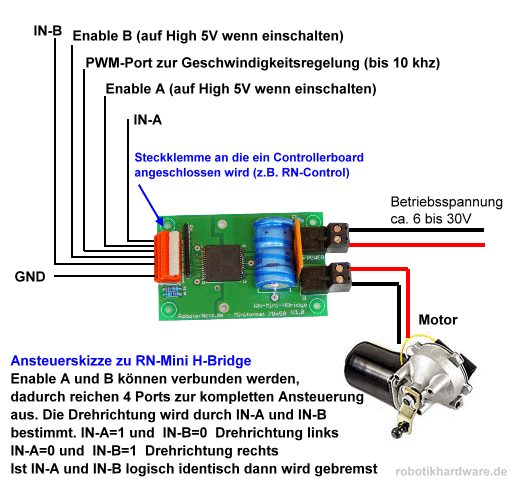
If you do some research you will find out that there are many other things which has to be considered in conjunction with h-bridges: Motors produce inductive currents on stopping which have to be discharged, the PWM-signal has to be applied to the motors power supply, not running at full speed will produce heat which has to be dissipated and also monitored. There are many things which can go wrong so I decided to look for an IC which is able to handle all these things for me. What I found is this http://www.shop.robotikhardware.de/shop/catalog/product_info.php?products_id=89 (I'm sorry this site is written in German). Only a few parts have to be assembled and once done the motor can be controlled by four pins at 5V-level:
  • IN A at high and IN B at low: The motor goes forward
  • IN A at low and IN B at high: The motor goes backward
  • IN A and IN B at high or low: The motor breaks if rotating
  • PWM: Input-pin for the PWM-signal
  • GND: The 5V-level ground
...and four pins at 12V-level:
  • POWER and POWER-GND: The place where the battery has to be connected.
  • MOTOR and MOTOR-GND: The place where the motor has to be connected.
Pretty easy, isn't it?


Once I have received the parts (including the IC used as the h-bridge) I will do the assembling and report about it in an upcoming post.

Donnerstag, 23. Januar 2014

Control motors - Part 3: Digital PWM

During the last days I did some research because I'm about to order several parts needed for upcoming posts. But now this is done and I'm ready to share further findings.

After exploring PWM-signals I thought about how to control pulse width by using Raspberry Pis gpio-pins. At the very first moment it seemed easy: Take four pins and set any binary value controlled by software (0-15 means 6.66% for each step which is sufficient for my needs). A circuit will manage the current flow through resistors which values match the binary bit each gpio-pin represents. But studying the PWM-circuit shown in my previous post discloses that electric current has to flow in both directions through my resistors and using the potentiometer the value of the resistor on the way back is complementary to the value of the one the way there. This is what builds the typical PWM-signal. Building a circuit based on gpio-input behaving in this way seems to be pretty complicated. There has to be a better way to do this.
After a little bit of searching the web I found this page: http://www.spaennare.se/pwmdig.html#chap6. The guy who shared this information (his name is Stefan) is pretty smart and found an indeed elegant way to solve this problem:
The cycle of a PWM-signal can be divided into units which number is defined by the resolution at which we want to control the output current. I my case this is 15 because I want to use four gpio-pins (2^4=16 stages and 15 units between them). Stefan has chosen 100 stages so his circuit is a little bit more complicated as mine will be (but more precise). Each unit can now be at current (called high) or off current (called low). So for example if we want 13.33% output we have to keep the first two units of one PWM-cycle at high and the remaining 13 units at low.
So how could Stefan achieve this pattern? He COUNTED from zero to 100 and COMPARED each value to the requested (and inverted) level of current. If the second value is greater then it is high otherwise low. And this is periodically repeated. If the counter reaches 100 it starts at 0 again. COUNTING is done by the IC 4510 and COMPARISON by the IC 4585. The output of IC 4585 is exactly the PWM-pattern we need.
But his approach has three downsides which I want to get rid of:
First disadvantage is that he uses decimal units (100) which is not a numeric system supported by computers well. Computers use binary numbers because they only know high and low (a bit). You can use 7 bits to represent numbers up to 127 or 6 bit for numbers up to 63. 7 bits wastes some space and 6 bits is to small. So using any potential of two for the number of steps will fit better to Raspberry Pis gpio-pins. So I will use the IC 4029 which is a binary counter instead of the IC 4510 which is a decimal counter.
The second downside is that his circuit needs an inverted input-signal for working properly. Inverting the signal is not hard to do (Stefan gives an example circuit) especially if it is provided by a computer: simply invert the number by software before setting the gpio-pins. But inverting is not necessary as you will see.
The third downside is that Stefan uses 100 stages from 0% (motor does not rotate) to 99% (motor rotates at almost maximum of speed). This missing step to get 100% of speed is not a problem at all. But if you use 4 bits (as I do) every missing step is 6.25% and a maximum speed of 93.75% is a problem!
So what have I done:
In my descriptions above I said that each step is 6.66%. This is because I use 16 stages which represent values from 0% to 100%. Common binary counters (as IC 4029) use four bits and allow cascading for counting bigger numbers than 15 (they start at 0). As we use four gpio-pins we do not need to cascade (as Stefan needed to count up to 100) what simplifies the circuit.
Next is that I do not invert the input signal. So I also have to choose another output pin (in fact two of them: = and >) of the IC 4585 to get a proper PWM-signal.
The last action is to preset the counter at 1. This reduces to number of units by 1 but raises the output of the input-signal "1111" to 100%.
So at the moment I'm waiting for receiving the parts I ordered (including ICs 4029 and 4585). As soon as they arrive I will test my theory and update this post by appending the circuit and pictures. So stay tuned!

UPDATE: I added another post ("Control motors - Part 3: Digital PWM - Part 2") to comment what happened during building the circuit.

Freitag, 17. Januar 2014

Control motors - Part 2: PWM

"Control motors - Part 1" showed that there are less downsides on step motors than on gear-backed motors. Nevertheless to move a mowing robot of a weight of about 10kg (sometimes uphill) we need a force of about 2-4 Nm per wheel (having a diameter of 12 cm). Only gear-backed step motors can put about this level of force and those are rare and expensive. If you put gears between a wheel and a motor the motor has to rotate at the rate of the gears faster to achieve the same rotating speed of the wheel. A step motor needs 200 impulses to turn its axis around. So using a gear-backed stepper with a gear-ratio of 1:50 results in doing 26315 steps per second to gain a speed of 1 meter per second. As I found in the web it seems that stepper motors are limited to 2000 sometimes 3000 steps per second. Even if there is a stepper out there which is twice as fast it would be 4-5 times to slow. Another fact is that step motors have less torque the faster they turn. So I think this is it: I need to use ordinary gear-backed motors.

So the first challenge at using non-step-motors (ordinary dc-motors) is to control their speed. If you look at the specification of a dc-motor you will find the voltage they need to run. This value is valid for the full speed. If you want half of the speed you have to halve the voltage you putting on. But how can we achieve this by using Raspberry Pi's gpio-pins? As I said in my preceding post we have to use PWM (pulse width modulation). But what is PWM and how does it work?

PWM means switching an electric current on and off very fast. Depending on the frequency of this switching the average voltage changes. This is very useful for digital controllers (as our Raspberry Pi is) which only know 0 and 1 (current off or on).
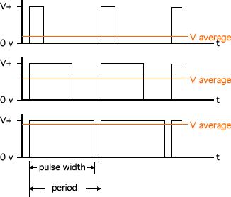
But PWM is a special way of switching current on and off: Within a period of a choosen frequency electric current is switched on and off proportionately. I found this image at http://www.societyofrobots.com which shows how it works very well:

These three examples use all the same frequency but different pulse width (electric current is switched on) and they produce different values of average voltage.

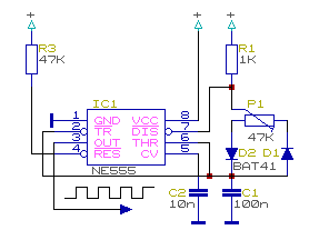
For my first actual project I decided to build PWM as a curcuit. In the electronic tutorials I looked at the NE555 IC was used to produce timed signals. I bought the parts for exercising those tutorials, so let's ask the world for instructions. I googled and found http://www.domnick-elektronik.de/elek555.htm (written in german) showing this tiny curcuit:

I built this curcuit on my breadboard and put a LED and a proper resistor on OUT (pin 3 of NE555). Guess what: The LED dimed by turning the potentiometer. For educational reasons I replaced C1 by 10ÎźF and voilĂ : The LED blinks in the way of the PWM signal.

UPDATE:
Here is a video showing the result:

Donnerstag, 16. Januar 2014

Control motors - Part 1: What type of motor to use

The first thing I want to do is to control a motor. For a mowing robot we need several motors: Those which drive the wheels and the one which drives the cutting-rotor.
Maybe this is the right moment to think about steering: As other robots do, I want to use three wheels. Two wheels at the back which drive the robot and cannot turn. One wheel at the front which is not driven but can be turned around at random. Here is an image: http://www.ratgeberzentrale.de/uploads/tx_news/15260_23529_Bild3.jpg. It does not show the configuration of the mowing robot I have in my mind but it does shows how the three-wheels-concept is meant.
In this configuration steering to the left is done by braking the left wheel or accelerating the right wheel. Steering to the right vica versa. An advantage of this technique is the ability to turn around nearly in place. A disadvantage is the need to control two motors precisely which means to use more gpio-pins than if we would drive our robot like a common car (I will explain the reason for this in an upcoming post).
So how is a motor controlled by an electronic circuit?
One possibility is to use a stepper-motor. These motors allow to turn a predefined step (for example 1.8°) forward or backwards. Repeatingly doing steps results in a continuous rotation. Speed is controlled by the interval of those steps.
The advantages of those motors are that they are easy to control and the force needed to do a step (even if you are driving uphill) is regulated by them self. Another feature is that they are able to hold their position even if a force tries to change the position. A downside of this is that they consume energy even if they are not rotating. Another disadvantage is that step motors are not built to rotate fast. They are made to move sheets of paper in printers forward and backward or support balanced robots for example. So it might be that this kind of motor is not suitable for our application.
The second possibility is to use back-geared motors. They are quite simple: put voltage on it and the axis starts to rotate. This kind of motor is not able to rotate slowly so the gear slows it down and brings additional power due to its gear ratio. This sounds pretty good but there are downsides!
The first one is the way to control the speed of rotation. This is done by reducing the voltage. If you have a regulator this is done easily but how can this be achieved by Raspberry Pis gpio-pins? The solution for this is PWM (pulse width modulation). This technique is supported by Raspberry Pi nativly but only for one device not two (motors). So we have to build PWM on top on usual gpio-pins. The second downside is that driving uphill would slow down the speed  of the motor and voltage has to be increased to compensate the reduction of speed. To do so it is necessary to measure the current speed - also not so easy.
As you can see the decision is not easy to come.