On our company's Christmas celebration (December 2013) all employees got a small present: A Raspberry Pi. This was the initial event for me to investigate what (internet of) things can be done driven by this tiny computer.

This blog is to document my findings and to share what others shared with me.

Posts mit dem Label pwm werden angezeigt. Alle Posts anzeigen

Samstag, 8. März 2014

Control motors - Part 3: Digital PWM - Part 2

When I wrote "Control motors - Part 3: Digital PWM" I thought everything would work fine but time told me different (in German we say: theory is gray but practice is colored).

The first thing I built was the clock. To make development easier I used a slow clock and put a LED at the output to visualize the signal:
This was pretty easy.

The next step was to install the counter. One thing I had to change was to count down instead of up because presetting to 1 by using the cascading output did not work: the signal is high from the beginning of 0 until the end of 14, becomes low in the middle of 15 and high again at the end of 15 (which is equal to the beginning of 0). I had to invert the signal since the preset-pin is low in inactive state but this means that the rising from low to high used to preset a value is in the middle of 15 - not at the end! This shortcuts the last unit.
A possible solution could be preseting the value asynchronously (which means to tell the IC within a clock-cycle to use the presetted value at the beginning of the next clock-cycle) but unfortunately the ICs I bought did not support this feature. Another solution is to delay the signal for the half of a clock-cycle by inserting a capacitor. This didn't work either. Additionally this way seems unstable to me. I always prefer to use things in the way they ment and if an IC does not support a feature I have to find another which does.
At the end I had to count from 15 to 0 and preset the value to 15 once 0 (= minimum-pin active) is reached:
The LEDs from right to left: Bit 4, bit 3, bit 2, bit 1 and the clock-signal. The IC counts from 15 to 1 and then starts at 15 again.

In the last step I added the comparator IC. I simulated the input-values (the percent of the PWMs duty-cycle) which will be given by Raspberry Pi's GPIO-pins by using four microswitches - each for one bit. Let me show you the possible input and output-values:
Signal sent by GPIO-pins Condition Output-signal
0-0-0-0 = 0 > or = to counter always 0 (= 0%)
0-0-0-1 = 1 > or = to counter 1 if counter is 1 otherwise 0 (= 6.67%)
....
1-1-1-0 = 14 > or = to counter 1 except counter is 15 (= 93.33%)
1-1-1-1 = 15 > or = to counter always 1 (= 100%)
As you can see this is a clean PWM-signal from 0% to 100%. And here is the video showing the signal:
In the middle of the breadboard is a blue LED showing the PWM-signal. At the beginning there is no light because no microswitches are pressed which means input 0-0-0-0 (= decimal 0 = 0%). Then I pressed the switch for bit 1 which means 0-0-0-1 (= decimal 1 = 6,67%). Next I pressed the switch for bit 2 which means 0-0-1-0 (= decimal 2 = 13,33%). Afterwards I pressed the switch for bit 3 which means 0-1-0-0 (= decimal 4 = 26,67%). And finally I pressed the switch for bit 4 which means 1-0-0-0 (= decimal 8 = 53,33%). To complete the row I pressed all switches additionally which means 1-1-1-1 (= decimal 15 = 100%). In every state the output-LED shows the proper duty-cycle.

At the end I replaced the big capacitor of the clock by a smaller one and the LED switched from blinking in the rhythm of the PWM to lighten more or less brighter - as expected. But suddenly the 0% stage was not "no light" instead it was slightly lightening even hard to see. Where is this current coming from?
This short video shows the breadboard in the dark. The clock-LED turns on and off so fast that it seems to be turned on continuously. The blue-LED which shows the PWM-signal is slightly lightened although the input-signal is 0-0-0-0 (no microswitches pressed).

Before I tell you, I have to admit that I had an error in reasoning: For the motors I want to use I have to apply a 2kHz PWM-signal. So I bought a capacitor for the clock-IC (NE555) to produce this frequency. But in fact if the desired PWM-frequency is 2kHz and we divide each cycle into 16 steps the clock for driving the counter-IC has to run at 2*16 = 32kHz.
Finally I could figure out that what I saw was the result of something called glitch. It occurs if the rising from low to high is to slow and the IC is to slow or clock signals delay due to long distances. So rising from 2kHz to 32kHz made glitches visible. As suggested by Stefan (see "Control motors - Part 3: Digital PWM") I replaced all ICs by pendants of the 74LS series. This didn't solve but cleared out the problem as these ICs switch faster:
Every time a cycle completed (counter has reached 0 and will be presetted to 15) the glitch is visible by a short blink of the output-visualizing LED.

But what is the solution? Generally it seems (as Google says) that a buffer should remove glitches. A buffer is a combination of two NOT-operations in serial. The resulting signal is the same as the original input-signal. Glitches should be removed because usually logical IC accept voltages below 1/3 as low and above of 2/3 as high. If the glitch is lower than 1.67V (5V * 1/3) than the buffer should clear out the correct signal. But this did not work for me. I assume that my glitch is near to 1/3. So I had to find another solution.
Finally I figured out that this also can be achieved by using a flip-flop. A flip-flop is the mechanism which enables a computer's memory to store binary stages (true or false => 1 or 0 => high or low). They work in this way: You have to provide an input-signal and tell the flip-flop to store that input. From now on, even if the input changes, the stored signal is provided at the output. There are several types of flip-flops but I used the D-type which depends on a clock signal. So the solution is to ignore values (also glitches) within clock-cycles and use the value at the beginning of a cycle (doing a snapshot by using the flip-flop) during the whole cycle. And indeed it works like a charm.
This was the first problem in electronics which I solved on my own. No Google - just thinking. I was very proud at this moment :-)
The ICs from the left to the right: flip-flop (SN74LS74AN), or (SN74LS32N), comparator (SN74LS85N), counter (SN74LS191N) and time (TLC555). In this version I replaced the microswitches by pull-up-resistors.

In the next weeks I will build a lead frame and a circuit diagram for this. I will update the post by adding these two things as soon as this is done.

Donnerstag, 23. Januar 2014

Control motors - Part 3: Digital PWM

During the last days I did some research because I'm about to order several parts needed for upcoming posts. But now this is done and I'm ready to share further findings.

After exploring PWM-signals I thought about how to control pulse width by using Raspberry Pis gpio-pins. At the very first moment it seemed easy: Take four pins and set any binary value controlled by software (0-15 means 6.66% for each step which is sufficient for my needs). A circuit will manage the current flow through resistors which values match the binary bit each gpio-pin represents. But studying the PWM-circuit shown in my previous post discloses that electric current has to flow in both directions through my resistors and using the potentiometer the value of the resistor on the way back is complementary to the value of the one the way there. This is what builds the typical PWM-signal. Building a circuit based on gpio-input behaving in this way seems to be pretty complicated. There has to be a better way to do this.
After a little bit of searching the web I found this page: http://www.spaennare.se/pwmdig.html#chap6. The guy who shared this information (his name is Stefan) is pretty smart and found an indeed elegant way to solve this problem:
The cycle of a PWM-signal can be divided into units which number is defined by the resolution at which we want to control the output current. I my case this is 15 because I want to use four gpio-pins (2^4=16 stages and 15 units between them). Stefan has chosen 100 stages so his circuit is a little bit more complicated as mine will be (but more precise). Each unit can now be at current (called high) or off current (called low). So for example if we want 13.33% output we have to keep the first two units of one PWM-cycle at high and the remaining 13 units at low.
So how could Stefan achieve this pattern? He COUNTED from zero to 100 and COMPARED each value to the requested (and inverted) level of current. If the second value is greater then it is high otherwise low. And this is periodically repeated. If the counter reaches 100 it starts at 0 again. COUNTING is done by the IC 4510 and COMPARISON by the IC 4585. The output of IC 4585 is exactly the PWM-pattern we need.
But his approach has three downsides which I want to get rid of:
First disadvantage is that he uses decimal units (100) which is not a numeric system supported by computers well. Computers use binary numbers because they only know high and low (a bit). You can use 7 bits to represent numbers up to 127 or 6 bit for numbers up to 63. 7 bits wastes some space and 6 bits is to small. So using any potential of two for the number of steps will fit better to Raspberry Pis gpio-pins. So I will use the IC 4029 which is a binary counter instead of the IC 4510 which is a decimal counter.
The second downside is that his circuit needs an inverted input-signal for working properly. Inverting the signal is not hard to do (Stefan gives an example circuit) especially if it is provided by a computer: simply invert the number by software before setting the gpio-pins. But inverting is not necessary as you will see.
The third downside is that Stefan uses 100 stages from 0% (motor does not rotate) to 99% (motor rotates at almost maximum of speed). This missing step to get 100% of speed is not a problem at all. But if you use 4 bits (as I do) every missing step is 6.25% and a maximum speed of 93.75% is a problem!
So what have I done:
In my descriptions above I said that each step is 6.66%. This is because I use 16 stages which represent values from 0% to 100%. Common binary counters (as IC 4029) use four bits and allow cascading for counting bigger numbers than 15 (they start at 0). As we use four gpio-pins we do not need to cascade (as Stefan needed to count up to 100) what simplifies the circuit.
Next is that I do not invert the input signal. So I also have to choose another output pin (in fact two of them: = and >) of the IC 4585 to get a proper PWM-signal.
The last action is to preset the counter at 1. This reduces to number of units by 1 but raises the output of the input-signal "1111" to 100%.
So at the moment I'm waiting for receiving the parts I ordered (including ICs 4029 and 4585). As soon as they arrive I will test my theory and update this post by appending the circuit and pictures. So stay tuned!

UPDATE: I added another post ("Control motors - Part 3: Digital PWM - Part 2") to comment what happened during building the circuit.

Freitag, 17. Januar 2014

Control motors - Part 2: PWM

"Control motors - Part 1" showed that there are less downsides on step motors than on gear-backed motors. Nevertheless to move a mowing robot of a weight of about 10kg (sometimes uphill) we need a force of about 2-4 Nm per wheel (having a diameter of 12 cm). Only gear-backed step motors can put about this level of force and those are rare and expensive. If you put gears between a wheel and a motor the motor has to rotate at the rate of the gears faster to achieve the same rotating speed of the wheel. A step motor needs 200 impulses to turn its axis around. So using a gear-backed stepper with a gear-ratio of 1:50 results in doing 26315 steps per second to gain a speed of 1 meter per second. As I found in the web it seems that stepper motors are limited to 2000 sometimes 3000 steps per second. Even if there is a stepper out there which is twice as fast it would be 4-5 times to slow. Another fact is that step motors have less torque the faster they turn. So I think this is it: I need to use ordinary gear-backed motors.

So the first challenge at using non-step-motors (ordinary dc-motors) is to control their speed. If you look at the specification of a dc-motor you will find the voltage they need to run. This value is valid for the full speed. If you want half of the speed you have to halve the voltage you putting on. But how can we achieve this by using Raspberry Pi's gpio-pins? As I said in my preceding post we have to use PWM (pulse width modulation). But what is PWM and how does it work?

PWM means switching an electric current on and off very fast. Depending on the frequency of this switching the average voltage changes. This is very useful for digital controllers (as our Raspberry Pi is) which only know 0 and 1 (current off or on).
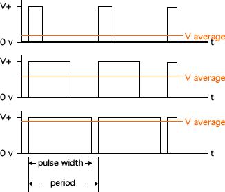
But PWM is a special way of switching current on and off: Within a period of a choosen frequency electric current is switched on and off proportionately. I found this image at http://www.societyofrobots.com which shows how it works very well:

These three examples use all the same frequency but different pulse width (electric current is switched on) and they produce different values of average voltage.

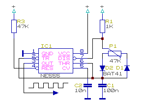
For my first actual project I decided to build PWM as a curcuit. In the electronic tutorials I looked at the NE555 IC was used to produce timed signals. I bought the parts for exercising those tutorials, so let's ask the world for instructions. I googled and found http://www.domnick-elektronik.de/elek555.htm (written in german) showing this tiny curcuit:

I built this curcuit on my breadboard and put a LED and a proper resistor on OUT (pin 3 of NE555). Guess what: The LED dimed by turning the potentiometer. For educational reasons I replaced C1 by 10μF and voilà: The LED blinks in the way of the PWM signal.

UPDATE:
Here is a video showing the result:

Donnerstag, 16. Januar 2014

Control motors - Part 1: What type of motor to use

The first thing I want to do is to control a motor. For a mowing robot we need several motors: Those which drive the wheels and the one which drives the cutting-rotor.
Maybe this is the right moment to think about steering: As other robots do, I want to use three wheels. Two wheels at the back which drive the robot and cannot turn. One wheel at the front which is not driven but can be turned around at random. Here is an image: http://www.ratgeberzentrale.de/uploads/tx_news/15260_23529_Bild3.jpg. It does not show the configuration of the mowing robot I have in my mind but it does shows how the three-wheels-concept is meant.
In this configuration steering to the left is done by braking the left wheel or accelerating the right wheel. Steering to the right vica versa. An advantage of this technique is the ability to turn around nearly in place. A disadvantage is the need to control two motors precisely which means to use more gpio-pins than if we would drive our robot like a common car (I will explain the reason for this in an upcoming post).
So how is a motor controlled by an electronic circuit?
One possibility is to use a stepper-motor. These motors allow to turn a predefined step (for example 1.8°) forward or backwards. Repeatingly doing steps results in a continuous rotation. Speed is controlled by the interval of those steps.
The advantages of those motors are that they are easy to control and the force needed to do a step (even if you are driving uphill) is regulated by them self. Another feature is that they are able to hold their position even if a force tries to change the position. A downside of this is that they consume energy even if they are not rotating. Another disadvantage is that step motors are not built to rotate fast. They are made to move sheets of paper in printers forward and backward or support balanced robots for example. So it might be that this kind of motor is not suitable for our application.
The second possibility is to use back-geared motors. They are quite simple: put voltage on it and the axis starts to rotate. This kind of motor is not able to rotate slowly so the gear slows it down and brings additional power due to its gear ratio. This sounds pretty good but there are downsides!
The first one is the way to control the speed of rotation. This is done by reducing the voltage. If you have a regulator this is done easily but how can this be achieved by Raspberry Pis gpio-pins? The solution for this is PWM (pulse width modulation). This technique is supported by Raspberry Pi nativly but only for one device not two (motors). So we have to build PWM on top on usual gpio-pins. The second downside is that driving uphill would slow down the speed  of the motor and voltage has to be increased to compensate the reduction of speed. To do so it is necessary to measure the current speed - also not so easy.
As you can see the decision is not easy to come.